|
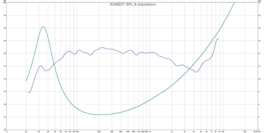
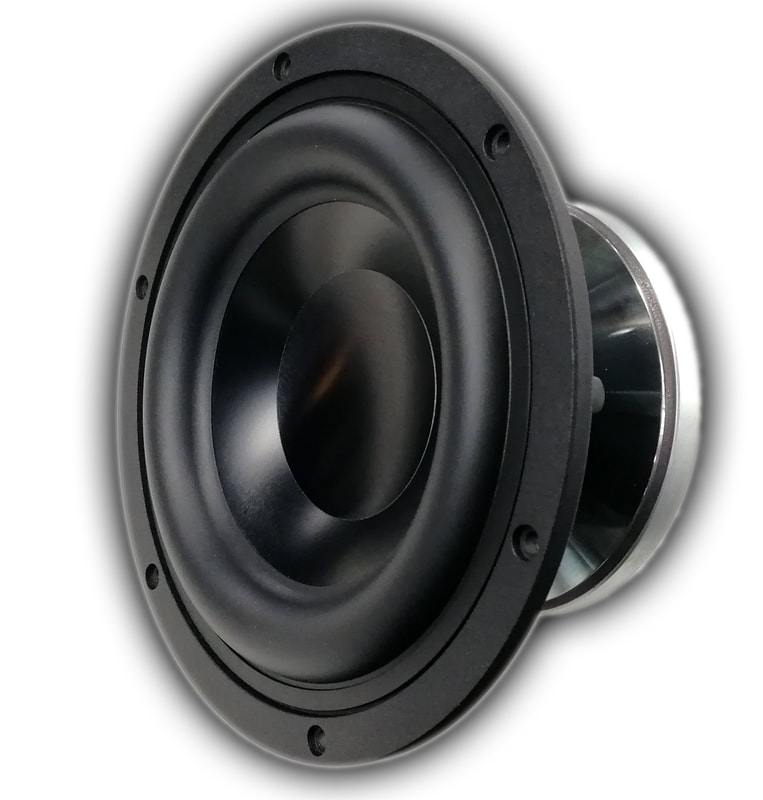
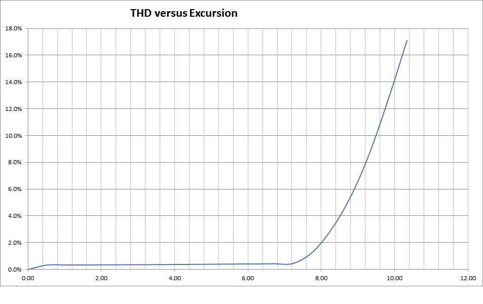
So what happened to you Mark? A whole year with nothing doing on the website. Well short but sweet two deaths in the family and all that follows the troubles that come with a father and a little brothers taking a dirt nap. Those problems have diminished and most of it is sorted out. So onward and upward. I was in China on an extended business trip this fall. Met a few great people at the Loudspeaker Sourcing Show in Nansha. A great meeting of people that are genuine producers and sellers of loudspeaker parts. From magnets to dustcaps and the enclosures to! If you are in this business and you are not going you have little idea what you are missing out on. Following that I spent a month in Guangzhou and surrounding cities working on and around some interesting projects. I was able to push through a really promising underhung driver that I designed. It is most probably the lowest distortion driver that I have ever produced. And I have have done a few that were highly regarded. So I'll share a few tidbits with you. So a little commentary on the graphs. The impedance response is smooth. No wiggles or bumps in the passpand that you would be applying this driver in. If you were using our tweeter you would be crossing over at 1200 hertz and the driver displays no nonlinearities at or around this level. Wiggles in the impedance usually correspond with wiggles in the phase response. Those wiggles are telltale signs of mechanical nonlinearities. Which are the causes of driver distortion. They are absent in this driver. There is a very low rise at resonance. How is that? Well the motor is underhung. That is the voice coil is always in the same magnetic gap. A very short coil and a very tall gap. More importantly is the linearity of the gap. I do a lot of FEA simulation before we take metal and magnet to make a woofer motor. The simulations looked good. When I measured the flux density in the gap I almost fell off of my chair. Linear within 0.04 Tesla from the top of the gap to the bottom of the gap. How tall is the gap you ask? Well 20mm tall I say. This driver will be able to crack 100db in a one cubic foot sealed enclosure. Not so bad. And all that with only 150 watts to boot! So now lets look at linearity. Remember that I simulated a linear flux density in the entire gap and was able to measure that same flux density within the gap. As one simulation holds true the others are now verified as well as they are bound together. Within a loudspeaker motor you have a fairly large source on non-linearity in the magnetic motor structure itself. A conventional tall coil small gap has a heap of nonlinearities. First and foremost is the varying inductance. Then there is the flux change as different sweeps of the coil pass the gap. These nonlinearities are expressed as distortion. In our motor we have a completely linear flux field along the entire length of the gap, from top to bottom. Inductance remains the same at any point. as does the flux or motive force against which your input signal from the amplifier works with or against to move the driver diaphragm in or out. A graph showing what I was just explaining. Under 0.5% distortion for 90% of your listening levels. Just shy of 100db actually at one meter or 93db at a normal listening position. And that is loud. Very loud indeed. Every driver will have rising distortion near it's limits in travel and this driver is not the exception. What is so remarkable is the wide travel available before there is even a start in the distortion products out of this driver.
Now a little talk about the frequency response. It's not flat!!! And that is on purpose! Take your standard driver application. This is a 7 inch O.D. driver. probably going into a 10 inch wide cabinet. An astute designer or a knowledgeable D.I.Y.er would be wanting to apply diffraction spreading compensation. Also known as baffle step response equalization. It's built in. You don't need to add it sacrifice 2 to 3db in the drivers baseline efficiency to create a passive EQ that will compensate for a small baffle. It's already accomplished. So the relative efficiency is what you get. It's actually pretty efficient in real applications. The SPL graph is done in a true anechoic environment. Not a nearfield farfield cut and paste or a compensated nearfield compensated for by massaging the vertical scale. This is a real 1/6th octave frequency response. I created a 1/3rd octave smoothing graph as per most marketing SPL graphs and just couldn't do it. I like to see peaks and valleys. They make the graph real. There will be more to come. These are measurements of the prototype. Stay tuned!
0 Comments
Leave a Reply. |
AuthorMark's Ramblings, show and tell. And other sundries. Archives
December 2019
Categories |
|
Service/Contact Hours
Monday: 9AM–5PM Tuesday: 9AM–5PM Wednesday:9AM–5PM Thursday: 9AM–5PM Friday :9AM–5PM Saturday: Closed Sunday: Closed |


 RSS Feed
