|
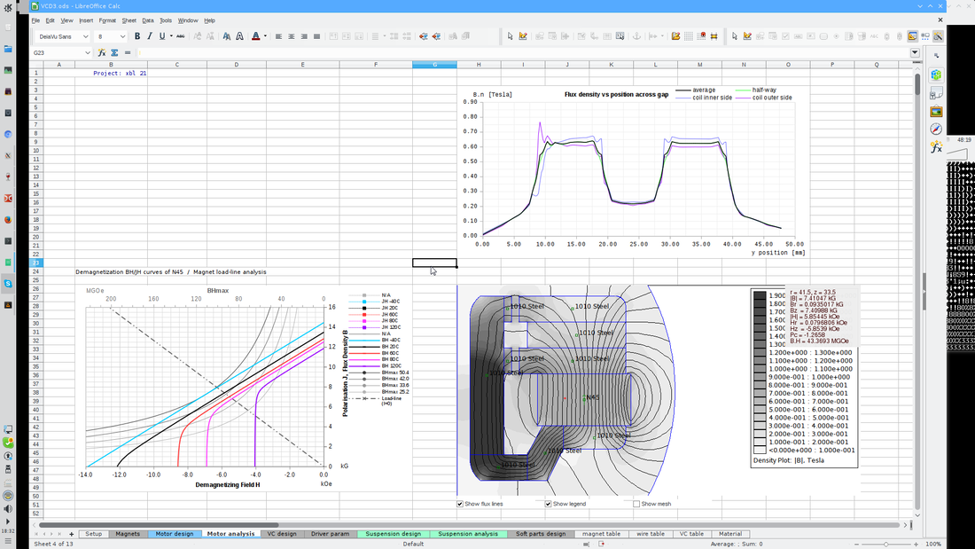
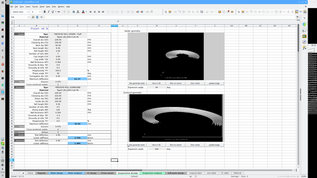
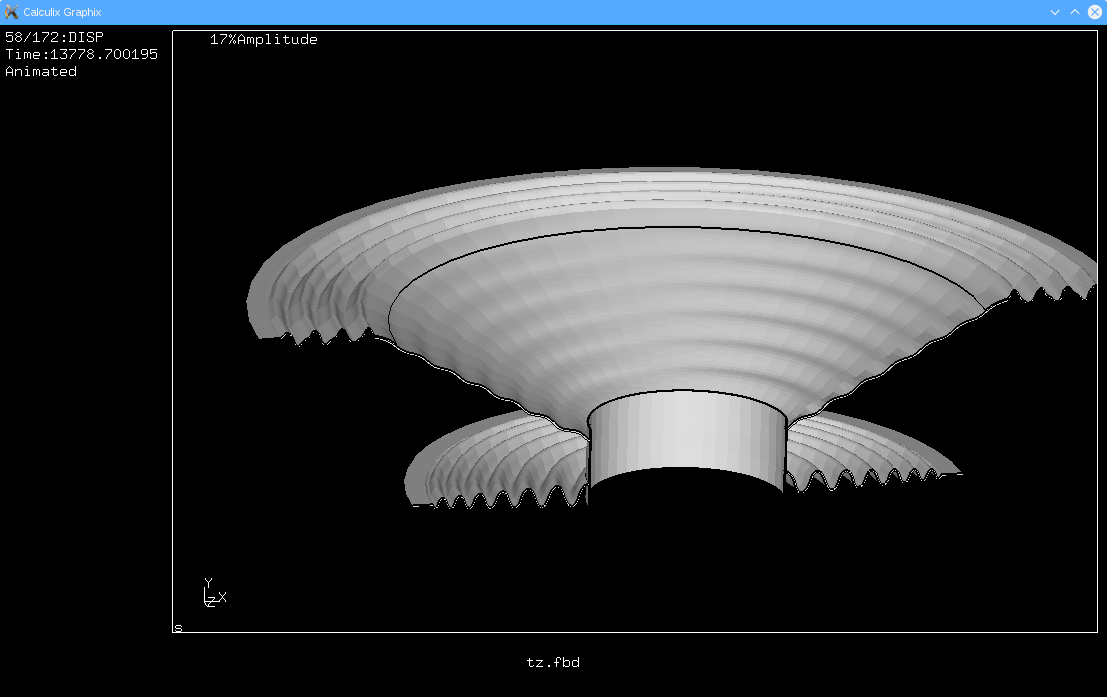
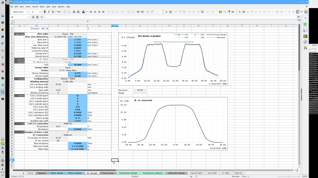
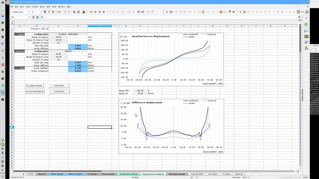
Well count me as about as busy as I can get in terms of audio work. I have a whole bunch of drivers that I have to setup to get produced. Clients that want all types of measurements. Almost makes sense when you think about it! And not enough time in the day to finish up drawings and tweak simulations. Let's just say I'm a little swamped. So on the good news front Akos our wizard of digital information is working his magic on the complete driver design program. I'm amazed at what he has put together from all of my research and his own research to. He is working on a program that can both design and simulate a loudspeaker from one end of the driver to the other. We can do all the design and simulation of the elements that make up the motor and the soft parts. That is the cone, the damper (spider) and the surround. Let's not forget the motor metal and magnet as well as the voice coil and former to. We both looked at what is being done with other programs and how we liked parts of them, but the available programs had design holes. Some programs like Fine Motor as an example can do the magnetics very well. We use the same magnetics FEA program for that work. FEMM by David Meeker. Other programs like Fine cone can do the cone and the surround. These two programs are mentioned because they are of very high quality. What we found missing in most programs was independent design of the voice coil. We have coil design tables from the major suppliers in round and ribbon wire as they have them available. So you are not designing something that you may have to pay extra for because it is not standard. Also from the start we worked on the ability to have multiple magnets and gaps. So you can work on more exotic very long throw motor designs. So some further pics: Magnetic flux lines through the steel on the bottom right. Magnet load lines on the bottom left. And the graph on the top right is rather interesting. The black line is the Magnetic flux across the gap and the two other coloured lines are the inside of the coil and the outside of the coil. Depending on your winding thickness there can be appreciable differences. And this promotes coil rock in some motor types. Knowing potential problems in advance is quite useful! Here we have a screen shot on the page that allows the design of spiders and surrounds. The soft parts of the loudspeaker. Materials can be described in the materials section of the spreadsheet. A still shot of the moving assembly. We can take it and simulate motion and look for potential problems and pitfalls. Top graph is flux density versus position and bottom graph is BL versus position. This is for a split gap XBL^2 type of motor. This page looks at the moving assembly in detail. The top graph is reaction force versus displacement. The bottom graph is suspension stiffness versus displacement. So some of these pics are new and some of them you may have seen before. We are using a standard driver design to work out the bugs in the spreadsheet. Now we are at the point where the proving out part begins. It is the point where we go from this driver design makes sense, to let's see if we can break the program! Three of us will be doing our best to test it out versus some real life drivers that we can all play with and measure then simulate and make sure we have something that is trustworthy.
Personally I really appreciate the value of a good simulation program. But I do not put blind trust into it. It is the same old axiom in anything to do with data. Garbage in equals garbage out. There are aspects of design that are quite accurate. I have had drivers measure exactly as simulated. And I can unfortunately tell you that some other drivers have been a bit more problematic. What this program will allow us is greater confidence in the areas that we did not have capability in before. Knowing the surround and spider excursion limits and their functional points of linearity are a big plus. Being able to design cone profiles, surround profiles and dustcaps is a great addition to the system we are currently using. And being able to simulate them in terms of additions or subtractions in the frequency response is also a big plus. What I have learned is that many programs are based on similar if not identical mathematics. Akos tells me regularly that what we are using in the background is giving us results that are almost identical to Comsol, Opera, or Vector fields or ANSYS. And the reason is quite simple. They all use similar math to get the results that they do. And there are good quality well supported Open Source programs that are just as accurate in their predictions. The trick is to be able to use them with the greatest ease possible.
0 Comments
Leave a Reply. |
AuthorMark's Ramblings, show and tell. And other sundries. Archives
December 2019
Categories |
|
Service/Contact Hours
Monday: 9AM–5PM Tuesday: 9AM–5PM Wednesday:9AM–5PM Thursday: 9AM–5PM Friday :9AM–5PM Saturday: Closed Sunday: Closed |
 RSS Feed
