|
I've done a lot of thinking over the past few months. Sometimes that can be positive. The concept of offering very unique and thoroughly engineered woofers midranges and tweeters has always appealed to me. Hence when we put together this website I made sure there were spaces and pictures as well as specifications for all these driver ideas. As people have been asking for these drivers I have had to say more times than I would like to that they are coming. I have no stock. I don't like to do that. If it's going to be on this website I want to be able to offer it. Short and to the point I can't afford to tie up money in driver inventory. Just keeping 100 pieces of each driver that I had spaces for on this website would cost me more than twice what I take home each year. Dead inventory is not income. And that had to change. But why???? Um.... this is a business. As in my source of income to keep paying the bills. Simplest answer that I can give is that selling drivers is not a quick and or easy way to develop an income. Especially when you are self financing. So what's the plan man! Loudspeakers. I have had the privilege of designing quite a few fully functioning loudspeakers over the years. They have gotten reviews as being very neutral clear and accurate reproducers of sound. And that makes me happy. Because that is what I was working towards in the first place! So over this winter I will be putting together a suite of very high quality finished loudspeakers. Some are totally new designs. Some are the fulfillment of previous designs that I can now do a little differently and a little better. So you designed loudspeakers for? Myself. Starting in 1989. Small monitor design using a Dynaudio 15W75 and a D28AF
CSS 2010 High efficiency design that never went public. These used Faital Pro woofers and planars from Akip. Funk Audio in 2011 I started helping Nathan redesign his subwoofer driver. The elements that made the greatest changes were the setup pf the magnet wedges in a spaced and indexed configuration and the angled radial cooling holes through the pole piece. I designed the 2 way, MTM and the large floor standing system that was displayed at the RMAF in 2013. The large format loudspeaker was never turned over to Nathan. He continues to use the front panel design that I did. Two designs that were described and discussed were a surround speaker that Nathan proceeded to try out and a wide band horn system with horn subwoofer. Those were design concepts. The details were never forwarded to Nathan. Volti Audio In 2010 and 2011 I worked with Greg Roberts of Volti Audio. He was looking for a design for a loudspeaker that he wanted to offer. He had a whole bunch of ideas. That was good. Ideas are the seed of getting things done. Over about 8 months I was able to work with Greg training him on how to measure drivers, measure rudimentary acoustic response of loudspeakers and walk him through quite a few design possibilities in a program called Hornresp. I ended up designing the bass section of the Vittora and the accompanied subwoofer. I also designed some cabinets for a very high priced Feastrex wideband driver that he was offering. Morrison Audio In 2010 I get a call from Don Morrison who introduces himself and he asks if I can design him a driver like the old Audire Audio Extremis. I can says I. He asks how much? A price is given and we agree to meet over beer and Pizza in Peterborough Ontario. Near half way between us for the two of us. He talks to me for about an hour and slides an envelop of cash. With a handshake we have been doing business ever since. I helped him modify and tweak the bass section of his Omni-directional point source as well as design his woofers and tweeters ever since. Unlike the other parties mentioned above (CSS, Funk Audio, and Volti Audio) Don actually pays his bills. If I had proper royalty payments from all parties profiting from my design work I would be in decent a financial position. So if you want to blame someone for the changes....
0 Comments
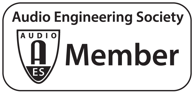
So we have been busy over here in the countryside of Perth Ontario. Some things are a foot as it were. Some of them even useful. I'll put up a few pictures: 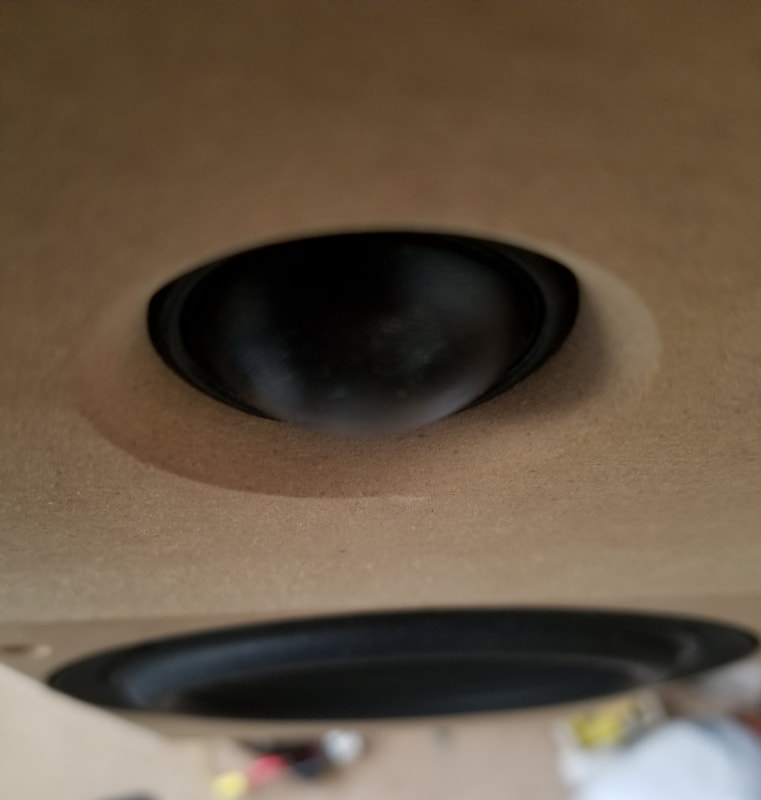 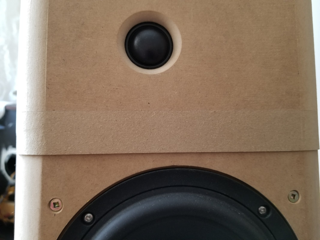 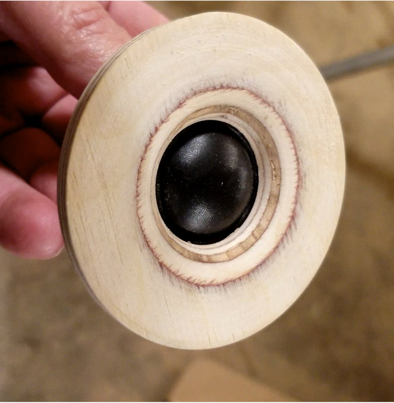 Some work on adapting a tweeter faceplate to our silk dome tweeter. It's a been a series of simulations, and prototyping of the simulations to get the desired effects. A dome tweeter on it's own is not really all that flat in frequency response. And the mount can have quite an effect on the final outcome. Our current tweeter mount for the car audio world was a quick and dirty version that is getting tweeked. It's response is getting a bit of a flattening as it were. The home audio version will be available in two versions a conventional 80 mm flange type and a larger waveguide/short horn. I'll address my definition of the difference between the two. I'll call something a waveguide if it only effects the dispersion pattern of a driver. It becomes a horn when it has an effect on the efficiency of the driver. Now don't get your knickers in a knot. A horn need not be a dirty nasal sound instrument of torture. A poorly designed horn can fit that description. We have all heard them right? Compression drivers on rectangular contraptions that breathed fire in the name of high frequency extension. Not. A properly applied horn especially with a hemispherical driver diaphragm can have a very undistorted output that has a rather well controlled on and off axis behavior. And it is to that stated goal that I aim to make a contribution. 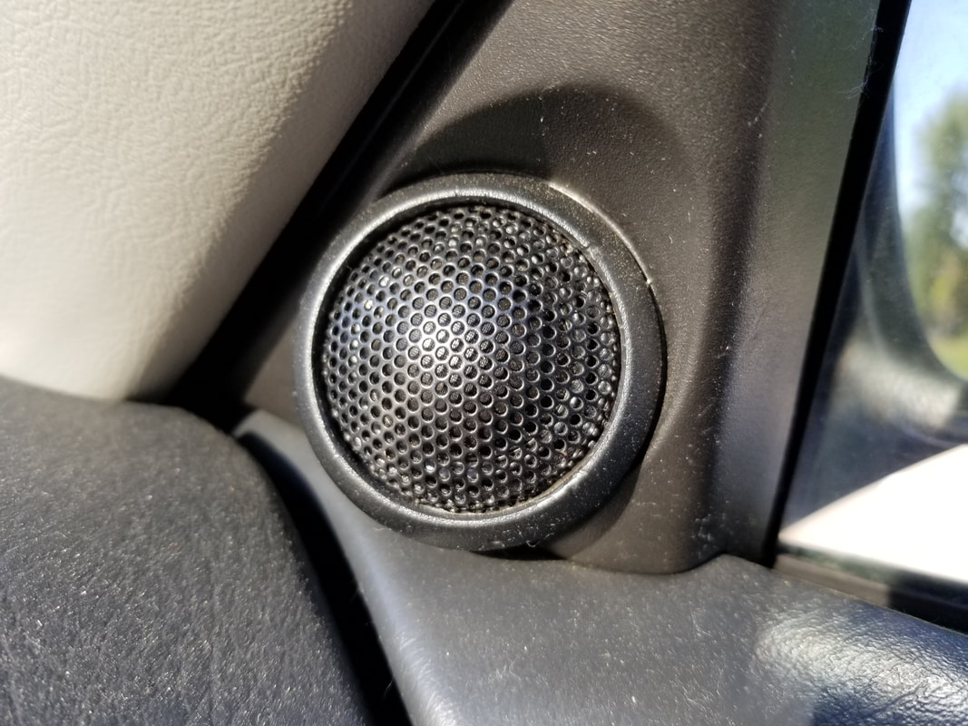 Cars? Tweeters?? I thought you don't have any for cars??? Well I don't have any of the fancy aluminum cups and mounts. But this is an example of mounting the raw tweeter into an existing factory tweeter location. 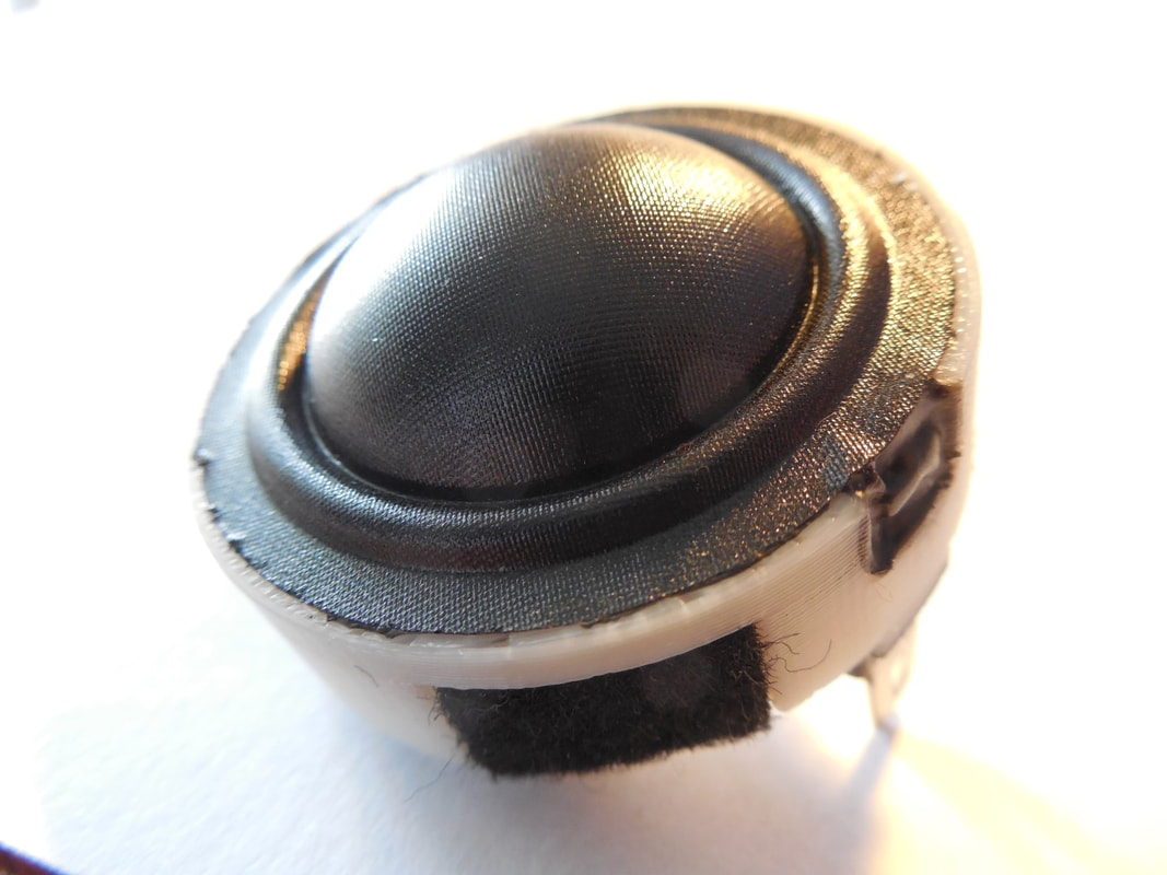 The outside diameter of this tweeter is 35 mm. My American friends can bet on 1 3/8" with a little bit of fudging the hole. There are few of these available if you are interested. They will be selling at $95 U.S.D. per piece. The new tweeter mounts are being designed and I expect them in the first few months of 2020. If you are interested in existing raw tweeter stock drop me an email and I will ship them out to you.
We have all heard the hyperbole. Analog forever. The pure sound of analog.. Need I keep going. Yes all of you in the front row are nodding and smiling. The ones in the back are wondering. What is this guy up to??? I'm not for one second saying that you cannot get great sound from a record. Nor am I slyly trying to say that digital recordings are the be all and the end all. I'm interested in the means and the methods used in service of either and or all of the above. After all I enjoy listening to music. I'm guessing that you do to. 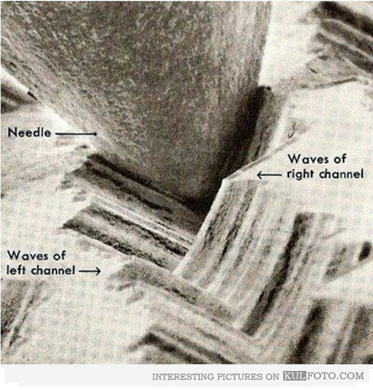 Let's get a little closer: 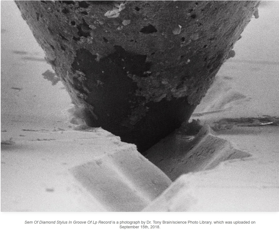 Now, really really close! 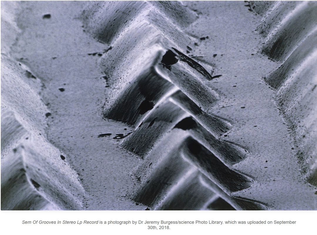 Those three pictures of canyons are record grooves. The first and second include the stylus and the third picture is magnified to give you a sense of the groove itself. Number three also shows a fair bit of wear. Something that is unavoidable in the use and listening of phonograph recordings. So I started off this little blurb with a statement about compression. What do I mean? Well lets start with how a recording is prepared for being cut onto record master on a record cutting lathe. You may think that microphone, perhaps pre-amplifier to power the mics, and then direct to a cutting lathe. Remember the direct to disc recordings that started in the later 70's? Well there was a circuit in between the microphone pre-amplifiers and the cutting lathe. So what does this circuit do? Behold the lines: 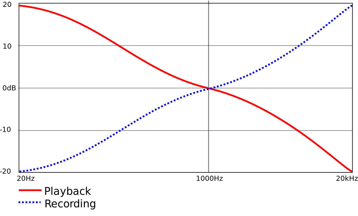 So to make a vinyl recording an equalization curve of the shape you see in the dashed blue line is created. A very simplified explanation is that the left side is the bass the right side is the treble. The line at 1000 hertz is within the beginning of our ears start most sensitive range. The vertical range is interesting. At 1000 hertz there is no equalization. At 20 hertz, fairly low in frequency there is a reduction of minus 20 decibels. It usually takes a 10 decibel cut in volume when listening to a speaker to say it is half as loud. So roughly a 20 decibel cut is going to sound one fourth as loud. To the right side of the graph you will see a boost of 40 decibels in relation to the cut at 20 hertz. That is a ratio of 10000 to 1 remembering that decibels are logarithmic. Not a linear scale as you would see on a ruler, or a tape measure . So the amount of boost and cut is not trivial. There is some serious compression of the signal.
Now this leads me to the mechanical side of a phonograph recording. Those pictures at the beginning of this post. Imagine how this works. Side to side and vertical movement of a single point cutter on a lathe will be used to convey the recording. As simple as it is complex. Record lathes are very complex pieces of equipment. The good ones are massive and cost near the same as a decent house. So lets recap. Our input signal from the microphones or master tape is really compressed on the low end and really boosted on the high end of the recording spectrum. Sent to a very highly engineered cutting lathe that creates a record master. (I'll leave out the negative creation and all that stuff) Then to play it back you take a needle that follows a single groove vibrating to the left and the right and a little bit vertically. That signal gets equalized again this time in the fashion of the red curve. 40 decibels of boost at 20 hertz and 20 decibels of cut at 20000 hertz. And you listen to it and marvel at how great it sounds. Some of the highest mechanical and electrical compression that mankind has been able to repeatedly manufacture. Record needles that may or may not be flat in their response. Playback equalization that again should follow a prescribed RIAA playback curve but not always. A mechanical playback method that by it's very design is susceptible to extraneous vibration. And a storage medium that from the first time you play the record you are wearing out a little at a time. Yep the analog sound. It amazes me that records can sound as good as they do. But make no mistake records so have a sound. the top end generally rolls off above 15 kilohertz. Not that big a deal as there is very little musical information up that high in the first place. The low end is usually rolled off and summed to mono below a prescribed midbass frequency that can vary from studio to studio. Even from recording to recording. But there is something that has not been mentioned yet. Modulation of the sound of one groove to the sound of the one beside it. That's right someone is humming along with your tunes ( Glen Gould need not apply). So yes there is an analog sound. And it can be rather convincing. I have listened to a displayed very high end record systems at a few RMAF shows in the past. I'll let you in on a little secret. I can be rather mischievous at times. I have done a few experiments of my own. I'll preable this story with a little explanation of another compression format. MP3 is a lossy compression format that if you use the higher bit rate of 320 kilobits per second can be rather useful to listen to music in a bit noisier environment like an automobile. So I have about 60GB of MP3 recordings that I have made myself from my collections of compact discs. I bring them with me pretty much everywhere. So back to Colorado and the Audio Festival. I had a group of people come into my demo room and I asked them if they wanted to listen to a recording. I played with the record player and sat down at my laptop and let them listen to a recording. They waxed eloquently of how there is nothing like the purity of the sound of vinyl. They could tell right of the bat that it was a truly quality sound system. They left. I asked our door man to lock the door and burst out laughing. He knew there was something fishy. They listened to an MP3. I motved towards the record player. Asked if they wanted to hear a recording and lowered the needle close to the record. Then I pressed play on Foobar2000 of a previously cued MP3. So what did I prove? I substituted a highly compressed recording in the place of another highly compressed recording. Both had high quality sources. Did I prove the old saying that people listen with their eyes? Probably. Did I prove the superiority of one recording compression method over the other? Hardly. I simply proved that a well done recording be it made in a number of different ways can give us a rather convincing facsimile of a live music event. And that my friends is what I'm after in the first place. Recreating as accurately as possible the original recording. Well I put up a playlist of making rather simple vented boxes.
They are made from what is often regarded as improper panel material for a good box. But I'll make a simple arguement that they are made from perhaps an ideal material for loudspeaker enclosures. It starts with why? Why are we making an enclosure in the first place? The answer is rather simple and two fold. Primary answer is that we are isolating the rear sound pressure generated by the backside of the cone. This has a certain degree of time or phase lag and when the pressure pulses that are made on the front meet the ones made on the backside we get a fairly large cancellation in the resulting sound pressure level. What's the second reason? Mechanical impedance matching. We are trying to match the volume of air behind a driver with mechanical suspension springiness also called compliance. This is much more important to get correct in a sealed enclosure than it is in a vented enclosure. To small of an sealed enclosure will limit your ability to generate excursion. This is the bane of many a subwoofer driver in a reasonably sized enclosure. You need a purpose deigned for a small enclosure to extract the maximum bass performance in a reasonably sized subwoofer. But.. I digress. Back to the OSB. A good candidate for a an enclosure panel would have a stressed skin type of a construction. One where you have an inner and an outer skin of stiff highly compressed material with a dampening layer in between them. So I have set you up to understand what the thicker OSB construction can provide. It is indeed the two stiff layers with a softer dampening layer between the two. So are there any sonic benefits? Probably! I will be doing some panel resonance videos in due time over the summer and we shall see. Using OSB is one of a few methods of constructing a cabinet that I have used of the years. It is not easier, it is not less time consuming if you want a good cabinet finish. But it does offer a clarity in the midrange that I have noticed and deemed worth the effort. OK forget the click bait young ladies. This video is actually quite interesting. A great analysis of modern pop music. Not a tear down of why it is good bad or awful. But why it is what it is.
I guess my going over to the darkside in 1984 has been a protection! So what happened to you Mark? A whole year with nothing doing on the website. Well short but sweet two deaths in the family and all that follows the troubles that come with a father and a little brothers taking a dirt nap. Those problems have diminished and most of it is sorted out. So onward and upward. I was in China on an extended business trip this fall. Met a few great people at the Loudspeaker Sourcing Show in Nansha. A great meeting of people that are genuine producers and sellers of loudspeaker parts. From magnets to dustcaps and the enclosures to! If you are in this business and you are not going you have little idea what you are missing out on. Following that I spent a month in Guangzhou and surrounding cities working on and around some interesting projects. I was able to push through a really promising underhung driver that I designed. It is most probably the lowest distortion driver that I have ever produced. And I have have done a few that were highly regarded. So I'll share a few tidbits with you. 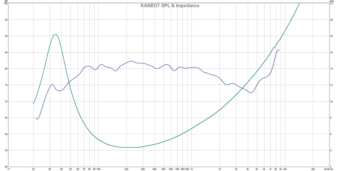 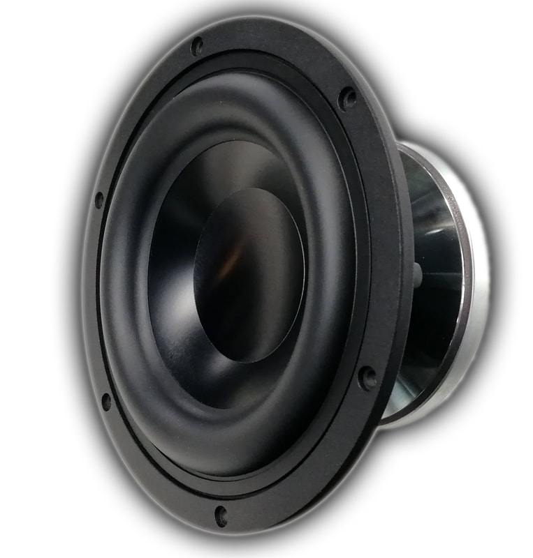 So a little commentary on the graphs. The impedance response is smooth. No wiggles or bumps in the passpand that you would be applying this driver in. If you were using our tweeter you would be crossing over at 1200 hertz and the driver displays no nonlinearities at or around this level. Wiggles in the impedance usually correspond with wiggles in the phase response. Those wiggles are telltale signs of mechanical nonlinearities. Which are the causes of driver distortion. They are absent in this driver. There is a very low rise at resonance. How is that? Well the motor is underhung. That is the voice coil is always in the same magnetic gap. A very short coil and a very tall gap. More importantly is the linearity of the gap. I do a lot of FEA simulation before we take metal and magnet to make a woofer motor. The simulations looked good. When I measured the flux density in the gap I almost fell off of my chair. Linear within 0.04 Tesla from the top of the gap to the bottom of the gap. How tall is the gap you ask? Well 20mm tall I say. This driver will be able to crack 100db in a one cubic foot sealed enclosure. Not so bad. And all that with only 150 watts to boot! So now lets look at linearity. Remember that I simulated a linear flux density in the entire gap and was able to measure that same flux density within the gap. As one simulation holds true the others are now verified as well as they are bound together. Within a loudspeaker motor you have a fairly large source on non-linearity in the magnetic motor structure itself. A conventional tall coil small gap has a heap of nonlinearities. First and foremost is the varying inductance. Then there is the flux change as different sweeps of the coil pass the gap. These nonlinearities are expressed as distortion. In our motor we have a completely linear flux field along the entire length of the gap, from top to bottom. Inductance remains the same at any point. as does the flux or motive force against which your input signal from the amplifier works with or against to move the driver diaphragm in or out. 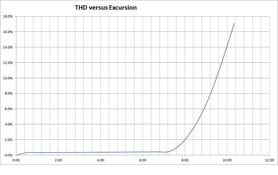 A graph showing what I was just explaining. Under 0.5% distortion for 90% of your listening levels. Just shy of 100db actually at one meter or 93db at a normal listening position. And that is loud. Very loud indeed. Every driver will have rising distortion near it's limits in travel and this driver is not the exception. What is so remarkable is the wide travel available before there is even a start in the distortion products out of this driver.
Now a little talk about the frequency response. It's not flat!!! And that is on purpose! Take your standard driver application. This is a 7 inch O.D. driver. probably going into a 10 inch wide cabinet. An astute designer or a knowledgeable D.I.Y.er would be wanting to apply diffraction spreading compensation. Also known as baffle step response equalization. It's built in. You don't need to add it sacrifice 2 to 3db in the drivers baseline efficiency to create a passive EQ that will compensate for a small baffle. It's already accomplished. So the relative efficiency is what you get. It's actually pretty efficient in real applications. The SPL graph is done in a true anechoic environment. Not a nearfield farfield cut and paste or a compensated nearfield compensated for by massaging the vertical scale. This is a real 1/6th octave frequency response. I created a 1/3rd octave smoothing graph as per most marketing SPL graphs and just couldn't do it. I like to see peaks and valleys. They make the graph real. There will be more to come. These are measurements of the prototype. Stay tuned! I'm Ears all Ears! So I was reading on a forum the other day about various viewpoints of people who make and listen to pretty good quality speakers. And I started to think. (yes dangerous we all know that) What gives with people thinking that there are multiple ways to setup and voice loudspeakers? Are we talking about different ears in every person ? There has been a lot of really good work done on exactly this topic. www.bksv.com/media/doc/17-197.pdf If you recognize the hairdos, you were alive and kicking back then (1974). I present this paper first because is it 43 years old. Think about this, There were measured and correlated best practices for the frequency response of loudspeakers 4 decades ago. Like I said what gives? www.dropbox.com/s/cty4728c8so4ic2/AES%20137%20The%20Influecne%20of%20Listeners%27%20Experence%2C%20Age%2C%20and%20Cultire%20on%20Headphone%20Sound%20Quality%20Preferences%20.key.pdf?dl=0 Sorry about the dead link! On a couple of decades we have the foundation for this paper written in 2015. Floyd Toole did a huge amount of work on what makes speakers sound best in the 80's. Along with him was Sean Olive and Paul Barton. There are very well researched and agreed upon methods of designing and setting up loudspeakers for the most accurate response. This is a summation that is pretty easy to read: www.innerfidelity.com/content/acoustic-basis-harman-listener-target-curve Now this article covers both Headphones and loudspeakers. There is a correction curve for how a headphone interacts with our head/ear system versus a loudspeaker in a room. The article covers both with a reference to how a loudspeaker system is defined, and characterized. Then setup as a reference for the sound you could expect from a really good pair of headphones. The results are interesting. So Pretending that you have not read all the references I'll tell you that in fact there are very well agreed to ways of "voicing" a loudspeaker to provide the most accurate reproduction of sound. I'll use the term voicing to cover the frequency contouring that is required in order to reproduce an accurate in room at listening position frequency response. So much of listening to good loudspeakers is linked to listening to good music live. Preferably un-amplified. To few people are taking the time to experience real acoustically (I use acoustically for lack of a better description) reproduced music. The best money spent to tune an audio system is to take time and pick out concerts. Listen intently. Get to know a few decent musicians. If possible try out their recordings on your system and hear how close, or far you are from what you remember. Our brains are adept at remembering pitch tone and timber of sounds we have grown used to. What ! Really! Again to many people have bought into the fallacy that you do not posses an auditory memory. Work with me for a minute here. Just think about the voices of people you know. How you can identify them without even seeing them. We all have the ability to create and strengthen our auditory memory. Like many skills practice makes perfect. Or at least practice makes for better than what you had! And if you are at that point of a great auditory memory already, a cultivated knowledgeable listener can then start looking at different recordings and if possible pictures of their recording sessions. How many microphones are they using? One per person? That is called mono miking. Or is there a stand out front with two mikes? That is a stereo pickup. The differences can be astonishing. 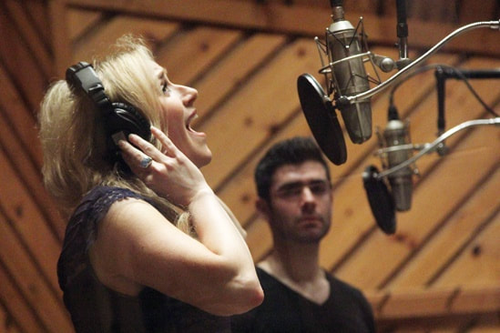 This is a mono microphone setup. One microphone for each individual. 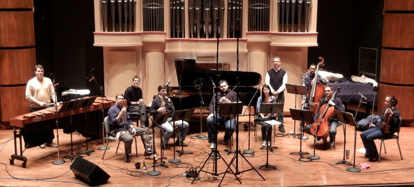 Combination of stereo pair as the main microphone pickup they are the ones high up over top in the front. The secondary microphones are for picking up soloists in the section. Note the spaced stereo pair beside the marimba. Let's play with this sad fact for a few moments. If you have ever listened to music reproduced acoustically in a reverberant space you know that there is the direct sound coming off of the instruments and the reflected sound coming from the room. That is pretty much how life works. Only outside in a wide open area or in a specially constructed room do you experience an anechoic acoustic field. That is one with no reflections. 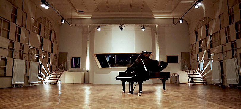 So I'm describing natural events that we all should be able to relate to. How you can close your eyes and listen to a person walk past you and you are given depth of space perception by means of the difference in timing between closer and farther sources of sound that are reflected to your ears and perceived by you ear brain system. We all do this and can experience this. And we do it without even thinking. Above is a reverberant recording studio.  Sad fact coming.
Pop music is almost universally recorded in a more or less acoustically absorbent studio (I'll qualify that the absorbent qualities are usually in the range that we use to locate and perceive spatiality). Recorded by one microphone per performer. Now wait a minute there! Doesn't stereo require two speakers? Isn't mono one speaker? So shouldn't a stereo recording require two microphones? That would be a resounding YES! But there are interesting timing tricks that allow a pseudo type of stereo effect to be generated. Reverb added in back instead of a live pleasing acoustic environment in the first place. One mic per person is also easier to setup in terms of making multiple takes in case of error on the part of the musician. I know more than one recording professional who has little to no hair after working with some groups. Single point miking is for the ease of creating an artificial ensemble. It is not an accurate means of making a stereo recording. It is a contrivance. So what do you do? Believe it or not I am not the originator of this line of reasoning (yes sad I am). There are great groups and recording engineers in almost every genre of music that have busted their humps to make real stereo recordings. Some labels are famous for their work in classical and jazz recording primarily with a stereo pair in the optimal position. So the answer is to look. Look for recordings and labels that are trying to do it right. You have a little bit of background now. And I'll follow up this post with a bit of information on recording microphones how they work and how they can be set up to create the illusion of people playing music infront of you. After all that's the entire reason why I got into this business in the first place! To listen to music. Well count me as about as busy as I can get in terms of audio work. I have a whole bunch of drivers that I have to setup to get produced. Clients that want all types of measurements. Almost makes sense when you think about it! And not enough time in the day to finish up drawings and tweak simulations. Let's just say I'm a little swamped. So on the good news front Akos our wizard of digital information is working his magic on the complete driver design program. I'm amazed at what he has put together from all of my research and his own research to. He is working on a program that can both design and simulate a loudspeaker from one end of the driver to the other. We can do all the design and simulation of the elements that make up the motor and the soft parts. That is the cone, the damper (spider) and the surround. Let's not forget the motor metal and magnet as well as the voice coil and former to. We both looked at what is being done with other programs and how we liked parts of them, but the available programs had design holes. Some programs like Fine Motor as an example can do the magnetics very well. We use the same magnetics FEA program for that work. FEMM by David Meeker. Other programs like Fine cone can do the cone and the surround. These two programs are mentioned because they are of very high quality. What we found missing in most programs was independent design of the voice coil. We have coil design tables from the major suppliers in round and ribbon wire as they have them available. So you are not designing something that you may have to pay extra for because it is not standard. Also from the start we worked on the ability to have multiple magnets and gaps. So you can work on more exotic very long throw motor designs. So some further pics: 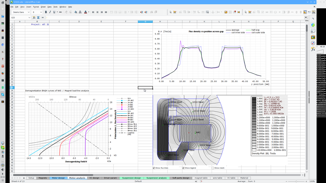 Magnetic flux lines through the steel on the bottom right. Magnet load lines on the bottom left. And the graph on the top right is rather interesting. The black line is the Magnetic flux across the gap and the two other coloured lines are the inside of the coil and the outside of the coil. Depending on your winding thickness there can be appreciable differences. And this promotes coil rock in some motor types. Knowing potential problems in advance is quite useful! 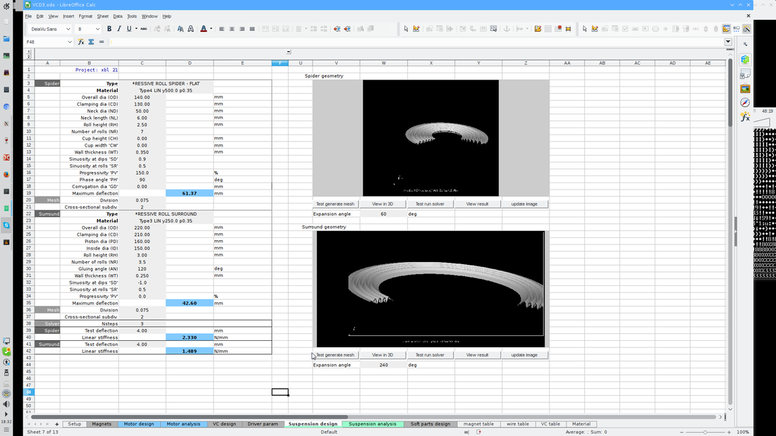 Here we have a screen shot on the page that allows the design of spiders and surrounds. The soft parts of the loudspeaker. Materials can be described in the materials section of the spreadsheet. 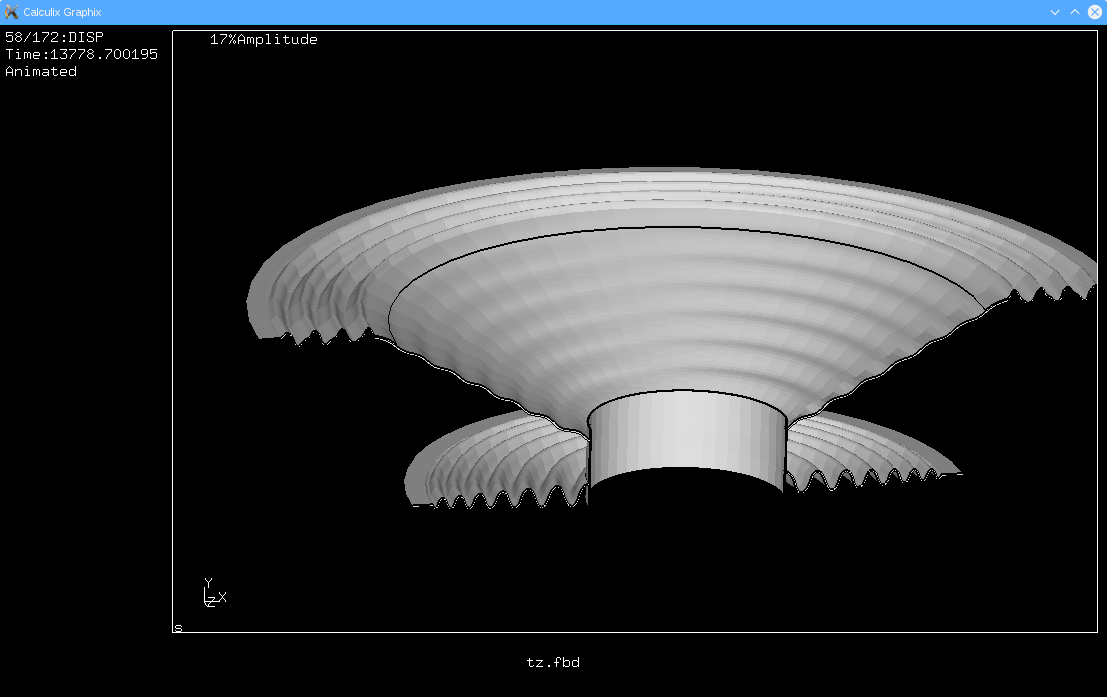 A still shot of the moving assembly. We can take it and simulate motion and look for potential problems and pitfalls. 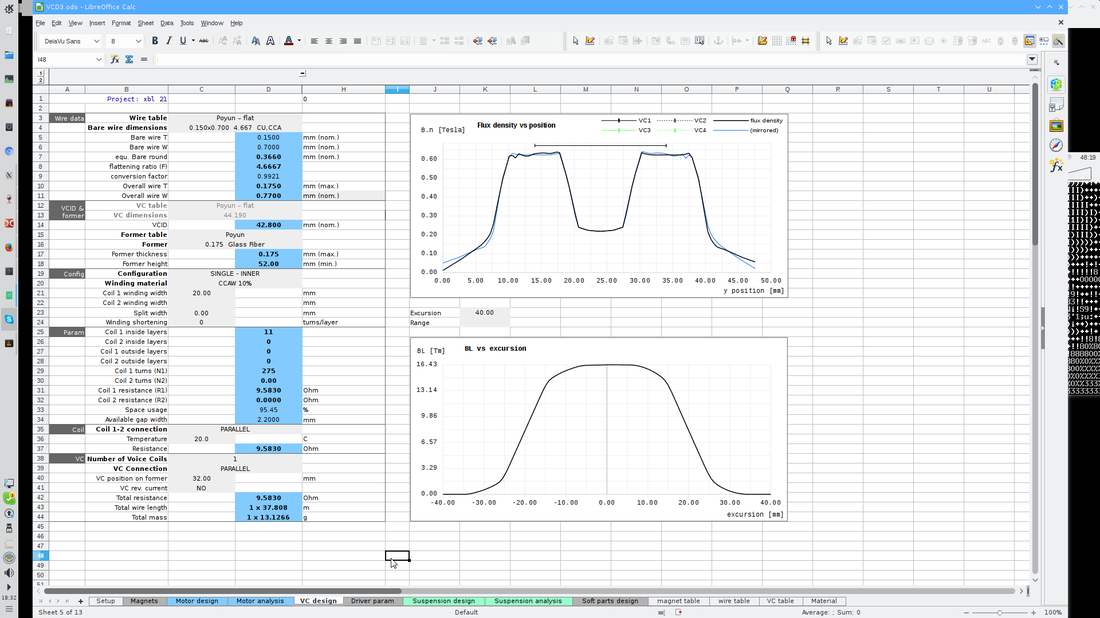 Top graph is flux density versus position and bottom graph is BL versus position. This is for a split gap XBL^2 type of motor. 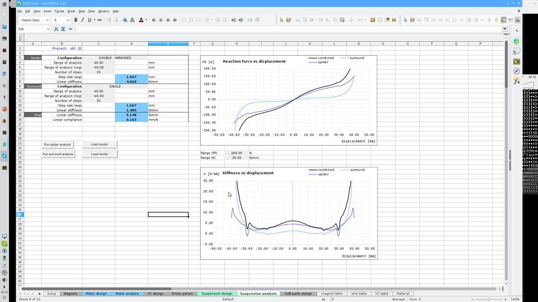 This page looks at the moving assembly in detail. The top graph is reaction force versus displacement. The bottom graph is suspension stiffness versus displacement. So some of these pics are new and some of them you may have seen before. We are using a standard driver design to work out the bugs in the spreadsheet. Now we are at the point where the proving out part begins. It is the point where we go from this driver design makes sense, to let's see if we can break the program! Three of us will be doing our best to test it out versus some real life drivers that we can all play with and measure then simulate and make sure we have something that is trustworthy.
Personally I really appreciate the value of a good simulation program. But I do not put blind trust into it. It is the same old axiom in anything to do with data. Garbage in equals garbage out. There are aspects of design that are quite accurate. I have had drivers measure exactly as simulated. And I can unfortunately tell you that some other drivers have been a bit more problematic. What this program will allow us is greater confidence in the areas that we did not have capability in before. Knowing the surround and spider excursion limits and their functional points of linearity are a big plus. Being able to design cone profiles, surround profiles and dustcaps is a great addition to the system we are currently using. And being able to simulate them in terms of additions or subtractions in the frequency response is also a big plus. What I have learned is that many programs are based on similar if not identical mathematics. Akos tells me regularly that what we are using in the background is giving us results that are almost identical to Comsol, Opera, or Vector fields or ANSYS. And the reason is quite simple. They all use similar math to get the results that they do. And there are good quality well supported Open Source programs that are just as accurate in their predictions. The trick is to be able to use them with the greatest ease possible. 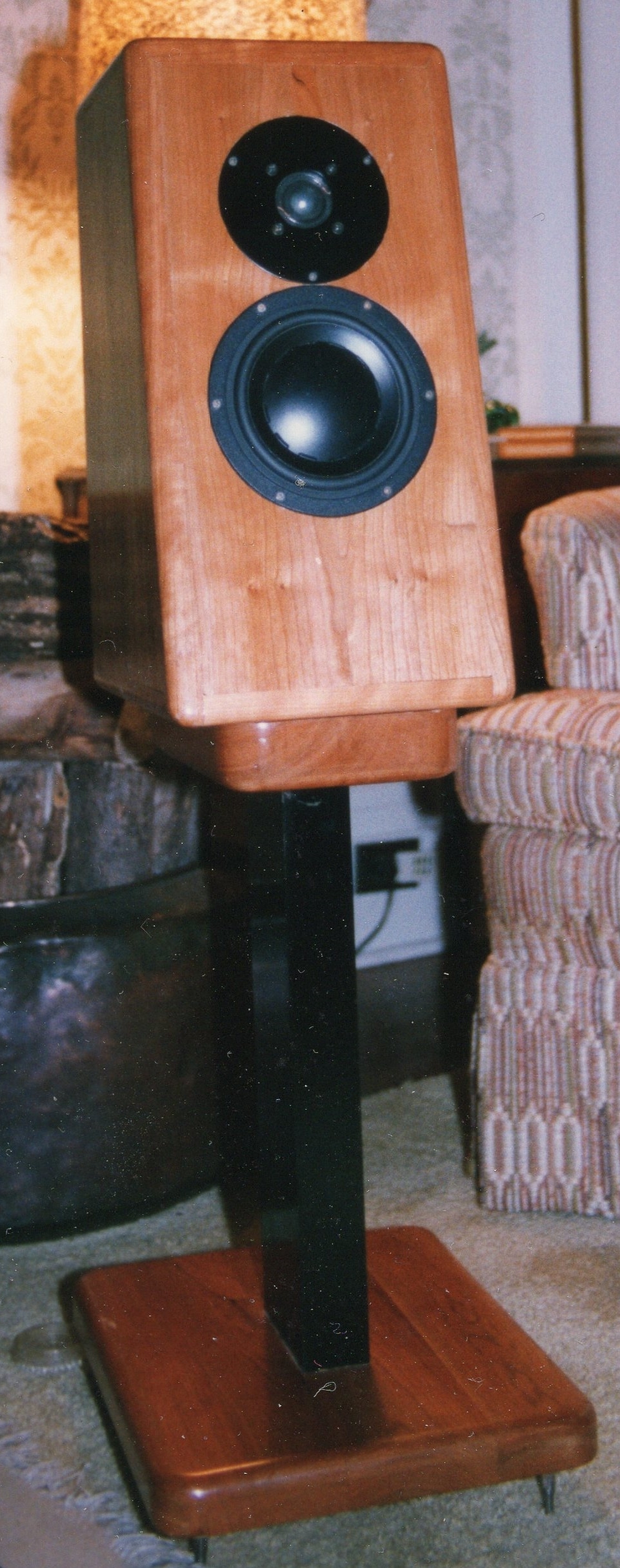 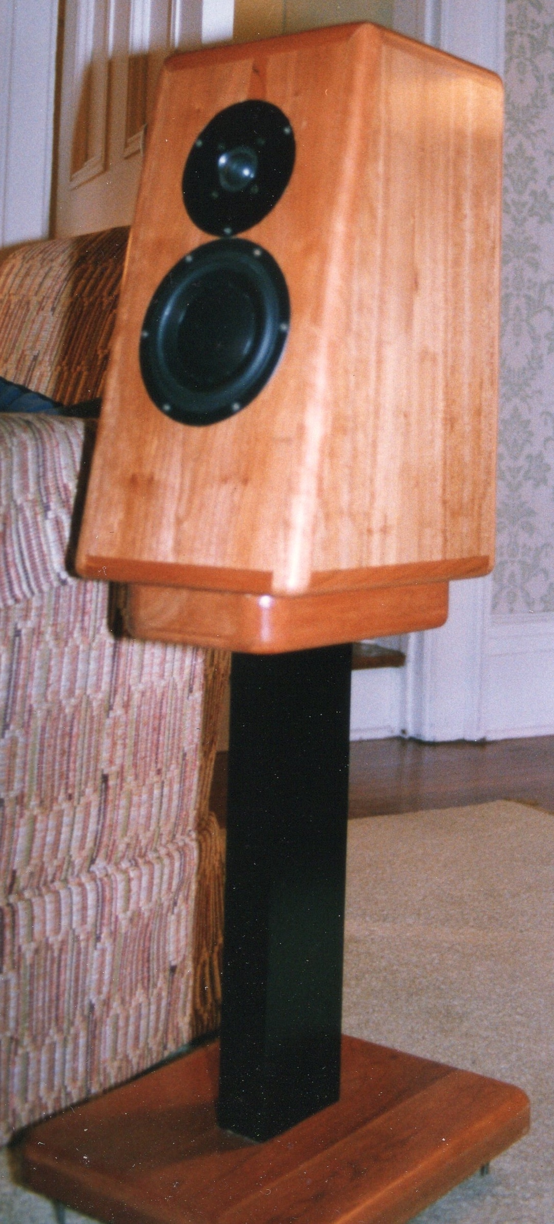 Dusty memories from 24 years ago.
From the long lost archives. This is the last pair of monitors that I worked on in The late 1980's. This set was made in 1993. Drivers were by Dynaudio. A 15W75 midwoofer and D28-2 soft dome tweeter. They sounded pretty good. The cabinet had a massive front baffle of 62mm (2 1/2") and a dual enclosure. The interior enclosure used a partial ellipsoid shape and the voids between this and the outer enclosure were sand filled. The ellipsoid inner volume was constructed in such a manner that it allowed a complete collapse of a reflection off of the back wall in half a wavelength. Sound waves bounced off of the rear wall and then reflected to a predetermined focal point and converged into a crisscross of counteracting reflections. It was a pretty successful design in terms of high quality audio reproduction. It's handicap was that it was a very expensive design from a company that had no real footing in the market. Lesson learned through the engineering was priceless. Lessons learned in unsuccessful marketing was equally priceless. Remember that this was pre-internet. This design was out at the same time as the original Totem Loudspeaker. In fact I had a good conversation with the designer of the Totem speaker at the 1989 Montreal Audio Show. Our discussion centered around the merits of the tweeter they used versus the Dynaudio tweeter. Then I was able to follow up that discussion with the owner of Solen Electronique (Denis Oullete) who was the supplier for both of us. Denis asked my opinion of how it sounded? My reply was "a cheap tweeter that was doctored up". "Exactly" was the reply. Then Denis and I traded ideas on the best crossover for my implementation. I think Denis taught me more about crossovers in that conversation than in any other one place. I stand on the shoulders of giants in this industry. From those generous enough to share their perspective and experience. That has been through the printed page and through one on one contact. Through emails and phone conversations in later years. The cabinet Fc was tuned to 45 hertz. And the little driver that we used could be rather great sounding in a medium sized room. The beginnings of understanding driver marketing were hitting me. The X-max Dynaudio presented was not specified as a plus or minus. Just total combined. The frequency response graph included a lowpass circuit for the woofer and a highpass circuit for the tweeter graphs. Things you learn along the way. Calculations were done using the loudspeaker cookbook and my good old TI calculator. Measurements via a function generator and a paper chart recorder and my trusty RadioShack SPL meter. You did what you could with what you had. Now we can do a little better! It's not everyday that you get a visit from a genuine audio dignitary, Nay his highness himself! The grand poopah of all things reproduced via sound waves. 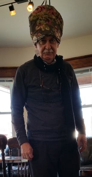 His highness paid us a congenial visit a few weeks ago and we are happy to share the outcome of his shared wisdom. "The money is in cables Mark!" So I got to thinking? "But you have to have something that has perceived value. Something not done by any other company." So into the left and insert two ear plugs I did (My best attempt at not loosing a thought). And this is what the KA brain trust came up with. 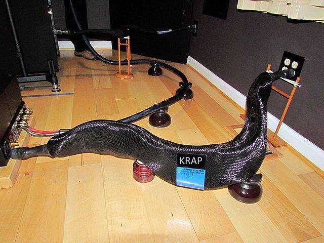 Yes you have guessed it. It's the Kravchenko Audio Reticulated Audio Pipeline. Never before has so little been presented as so much. The cable world will have to swallows it's pride and come over to the KA side.
A yet to be determined price in the 6 figures is what we have thought about. Dreamed about really. Really. No I'm not kidding. We figure if we sell three pair a year we could cover expenses. So we are looking for takers. On the speakers page of the store in this website you will find available some ready made baffles for a set of CBT loudspeakers. The baffles come with 26 pieces of a highly regarded wideband drivers and are purpose fitted for use.
They are the product of a design that I am no longer pursuing. I like the CBT concept. What I will be doing shortly is producing one with current drivers that are of my own design and manufacture.. Also available are four PowerSoft plate amplifiers that would make a great active CBT. If you are interested in this you know how to get a hold of me. This is a one time offer. When they are gone I will not be offering a CBT kit again. http://www.kravchenko-audio.com/store/p22/One_off_set_of_CBT_front_Baffles_and_wideband_drivers.html Many people who are looking at this site are in the audio business. Many are actually professional car audio installers. And some of them actually own their businesses. I have been blessed with people that give me great design advice for what works and what is not gonna work in car audio. And I really appreciate it. We are close to doing a run of the shallow 6.5 inch drivers. And I'm wondering if there is any further advice. Also wondering if there is enough demand out there for a appreciable run size. Comments are enabled below if you are willing to write down what you think. Hello DF.
Yes these drivers are still in the works. I'm about ready to pull the lever on a driver run of four different types. I have been workingon something that has a little better X-max than what I have been currently working with. Greater linearity over the full stroke versus the older XBL^2 design. Higher efficiency to! Last benefit is 1/2 the distortion of the XBL type driver. So I am pretty primed to get some of these out into the hands of knowledgeable people. I just received the usual daily dose of emails. Among them was a cool driver from Parts Express. It's their ES180TiA-8 model. Funny thing is that they use the same sized basket as I do. And I never considered my offering as a 7 inch driver. But upon taking a tape measure to the prototype basket in a nearby shelf I find it to be almost 7 1/8th inches in outside diameter. I squeeze a bit more Sd out the basket than did the engineer who designed it for Parts Express as I have the basket machined in strategic places to allow what I am looking for in terms of clearances. The basket is a very beefy design that has a great deal of potential. And I get a great surface area because the surround I use is custom designed for the sole purpose of a clean response and a long excursion. On that topic of surround for a clean response, I'm actually looking into making a double s type surround as well. It offers some further benefits in the higher frequency range.
Right now the surround we are using has a few applications of mass loading and dampening that have turned this driver into a clean mean pumping machine. ( oh yeah took me at least 30 seconds to think that one through! ) Displacement is one thing. But having a clean easy to listen to midrange is really the goal in a driver size like this. And an enormous amount of time on the design end was applied to making it so. Looking forward to the new batch coming. We are using the same custom cone, and a retooled surround to take advantage of the new motor's extra available excursion. So maybe I should rename the KA6.5 as a KA7? The 8 is actually larger than 8 inches to. Man all my model numbers are now out the door. Well off to start the tractor. Winter is still here in Ontario. And we just received a nice dump of snow. So time to clear away all 250 cm or 10 inches of the fluffy stuff. How much wood can I chuck?
Part of what makes us a different kinda company is that we design drivers, and we integrate drivers into finished products. Much of that kind of work is showcased in the Previous Commercial Products page under the services tab. From a value added perspective the creation of a loudspeaker is worth more to the end client than the constituent parts. Research and Development of loudspeaker drivers for OEM and DIY applications is an time consuming and expensive business. So to push this out into the open we are getting into to this in a modest way. Each model we are going to offer is a unique design entry in their respective design types. Our first finished product is almost ready. A two way very high efficiency horn loaded loudspeaker for home audio and theater applications. The model will be designated as the KA-HT-MAXX and is pushing the boundaries of what is currently available either in prosound or in home audio. Years of experience has taught me that some products simply do a job better than others. As an example high frequency reproduction can be done efficiently by a compression driver. It can also be done with high efficiency planar diaphragm drivers. The differences are interesting. Differences in the time you are comfortable in listening to the speakers are the greatest differences. They are linked to the amount of distortion products and the types of distortion products produced by the various drivers. Add to the mix that if you can use a horn loaded cone driver they to have a mechanical lever type of effect in that they can produce a pretty high output of sound for a relatively small movement of the cone. This is another reason why the sound reproduction can be dramatically clean from unwanted distortion products. Back to the wood chuck line. Part of what I personally enjoy in this field of endeavor is to actually fabricate finely crafted products. I have been behind the scenes training and coaching quite a few other people in producing high quality loudspeaker cabinets. There is enjoyment in engineering and testing to be sure. The pursuit of an idea along with the calculations required and validation of the calculations are of great interest to me. Those types of endeavors are part of every day over herein one way or another. And I have found also a similar type of enjoyment in pursuing the actual fabrication of these ideas and concepts into physical products. What changes a new year can bring in!
You may have noticed that we are creating a newly designed website. Steve is doing a wonderful job. And I help with content and text. A second set of eyes and ideas for my website is very much appreciated. You may notice that we have a few new sections. Mobile drivers, Professional drivers, HiFi Drivers and Speakers. We are close to setting up a funding source for some of the stuff. And I'm seriously considering a Kickstarter or Indiegogo campaign for two shallow woofers specifically designed for mobile audio. I'm busting my rear end to get a few prototypes out in the wild so I have some feedback. It simply takes money, lot's of money! The gentlemen are already chosen and they are knowledgeable users of high quality mobile sound drivers. Their feedback will be key to setting the stage for a funding run. As for other companies finished speakers. I have done a fair bit of commercial design for a few companies. I'm thinking of putting up a page showing the ones that have publicly acknowledged my input. I'll put in little bits of information about what I was able to provide in the way of either complete design or design assistance. Now for something a little different: It's about time to dive into the deep end of the pool and make available some of the stuff sitting in the design files. The kind of speaker designs that I did for others but held back on letting out into the hands of previous clients. There is a full complement of ideas. From bookshelf designs to really massive floor standing monitors. From the fertile mind of a loudspeaker designer to your home I guess. This is not intended to be a production run of anything. I'll do a limited run of speakers each year so that I can keep them under control. Availability will be on a first come first served basis. Each model will have a fully finished first run and when they are done, we will be putting up information. Each model will be offered in two formats, Active and passive. Passive will cost 50% more than active. It takes a fair bit of time to design and develop a good passive crossover. And to build them with quality components takes a fair bit of money. My personal preference is for doing the work with an active crossover and built in amplification with an active DSP network. I can also set up the speakers so you can provide your own amplifiers and I provide a pre-programmed DSP unit to do the crossover work. As a teaser I'll introduce what I have in mind. A point source partially horn loaded bookshelf. Horn loaded mid tweeter with woofer injection at the correct point for both wavelength and time alignment from within the horn. High efficiency design. Medium sized rear loaded horn WWTWW system. One in prototype stage has been running for a few years and continues to make me itch to let it out in the hand of others. Driver complement is 4 proprietary 5.25 mid-woofers and a medium sized planar mid tweeter. A high efficiency design. Larger driver complement of the same format. This will allow the system to plumb the depths of music and movie effects with great authority. It would have 4 proprietary 6.5 and a large proprietary planar mid tweeter. High efficiency design The big momma. I partially released a large format system when I was with Funk Audio. I built it and we exhibited it but the design was not transferred to Funk Audio. I have done some serious refining of the concept. Proprietary drivers with more than twice the X-max and redesigned rear loaded horn for effective in room response all the way down to 14hertz. I did it before. And time to do it again. High efficiency design. 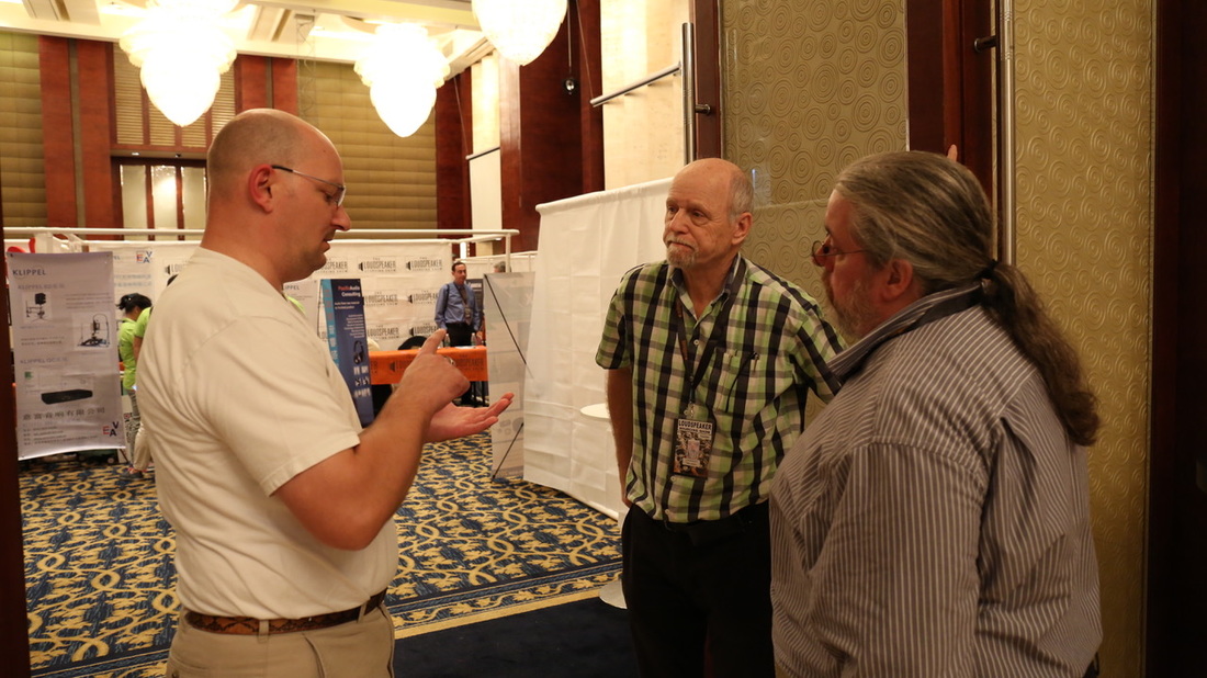 Right to left is Peter Andrews current ALMA president and Peter Larsen of LOUDSOFT.
We were discussing the ability to model loudspeakers driver parts with readily available open source tools. I'm near the end 1:16 to 1:21. I had the priviledge to give a presentation on Open Source Loudspeaker Modeling.
 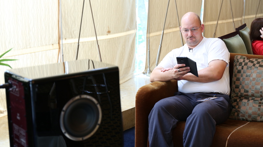 Some dude catching up on his emails. And enjoying the tunes coming out of the AvantonePro Abbeys. One sweet sounding loudspeaker. I had a small part in helping voice the originals pair. Another set of knowledgeable ears. Hats of to Mr. Craig Devin a great design and realistic price point.
I tend to post things that I hope will be of interest. Sometimes of no real connection to audio. I put up one off design work and custom work as a bit of a show and tell and a scope of capabilities over here.
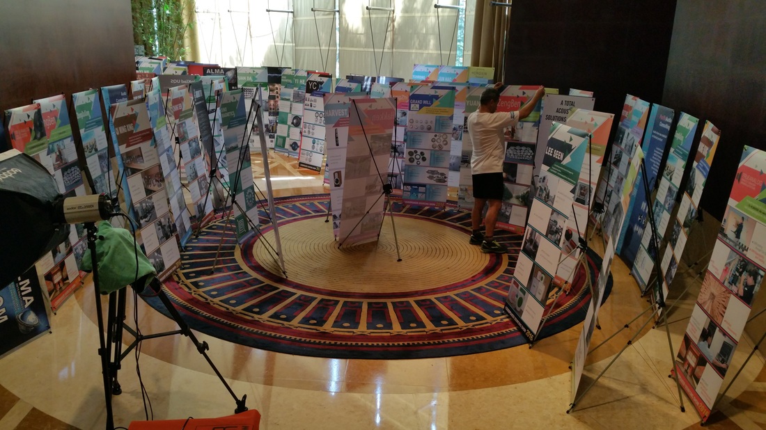
What does not get put up is what I consider the more mundane parts of this business. The testing, the measurement and the engineering part. Lot's of time staring at my computer screen. I think it is high time that that becomes a part of the audio engineering that I put up on this blog. Taking the opportunity to visit China these past two weeks has kind of opened my eyes to a few things. Having rubbed shoulders with a few very knowledgeable gents has motivated me to share a bit more. So in the weeks to come I will be putting up some different pieces of information. The topics will include some driver design points. Some info on the software that we are developing in house to facilitate the art of driver design to a little bit further degree of calculation. I had the opportunity to give a very brief presentation about the software at the Loudspeaker Sourcing show in Nansha. Many asked if I was going to release this software. My answer was pretty simple. I don't want to support it. That job is a thankless one. And the reason why so many programs are so expensive. The after sale support. There is a possibility of a simple direct share with no promises. That may happen. The software does not design speakers. The person directing the software does. So stay tuned. A few enclosures have to be finished as prototypes for a few clients. I will be posting some of the measurement and testing. And I will try and make it as interesting as I can. Questions are welcome as always. So is constructive criticism. 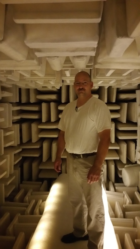 A little view of a guy in an anechoic chamber!
I just fit! I helped design and build this a few years ago. Nice to see that it is being put to good use. Well I'll be in China for a while in the beginning of October. Part meet and greet and part fact finding. Looking forward to both.
I will be coming back soon enough and will have more news as the month progresses. Looking forward to seeing some folks at the Loudspeaker Industry Sourcing Show. Looks to be a busy and fruitful gathering. If you want to talk to me I'll be the guy that looks like Shrek. No green paint unfortunately! Well summer has been a blast. Many things done. Many left to do.
I played around with the poll page. Not happy with the way it looks or works. That I will figure out how to make much better. I have tweeters almost ready to show up. A final payment is all that is required. They are raw drivers. And I have 8 empty car mount aluminum cup mounts in stock. I have a pair that are reserved for warranty. Yes I do warranty when it is my fault. I had a pair go out a while back that I did not clean up properly when assembling. Learned from the mistake. And now I don't have the same problem. A pair are already promised to one gent. So that leaves possibility for three pair. I will do a new run of car mounting enclosures that will address some of the comments that I have received about cup size and shape. And there will no longer be any push on connectors. I think almost universally the push on connectors were made into a wire tail and connected in that manner. And I have an idea that can make the tweeter mount as small as is possible. But that will take a trip to China and some explaining at the factory. A home version is almost ready. It will happen when I have my little prototype lathe going. Have to start off somewhere. I will end up doing them as needed out of black Acetal. It's a strong attractive plastic that is nice and easy to machine. New poll and new poll format.
New options and new potential drivers are there to vote for. Take a look and vote for what interests you. If it is not there drop me a line and I may include it. Currently I am working with our programmer to produce a very comprehensive software suite for the design and performance modeling of loudspeaker drivers. Specifically the soft mechanical parts and the motor magnetics analysis.
It is proving very fruitful. Concepts and simulations that were difficult to integrate into a loudspeaker design through a single program are now in a single integrated interface. This produces a smoother flow of work, and a general standard of calculation that builds confidence in the engineering calculations. Nothing is worse than trying to move some simulation results from one program to another and not really knowing the standards being applied in each case. The manuals only tell you so much. They leave out the actual bits that are most useful to the competent engineer. It is opening up quite a few opportunities for me. We are in the process of proving it out in comparison to results calculated with ANSYS and a few other big gun FEA applications. Vector fields and opera are the two other programs for comparison. So far the FEA comparisons are spot on. So from this point we go to real world versus simulation world. That is designing a motor as built, simulating it and comparing the simulations to the actual measurements. This builds confidence in the results. And is the only way I know of to really prove out the calculation methods. Why is this important? It should cut down on the design time and open up possible motor designs that would be difficult if not impossible with most commercially available software. How about 4 discrete motor gaps and 8 coils? Can do. Front and back spiders? Check. Double spiders? Yes sir. Inside and outside the former coil simulation? Done. How about flat wire or round wire? Standard voice coil dimensions from major suppliers? ( three at the moment ) Interactive spider designer? Interactive surround designer? Both soft part designs are run through potential stress points, mechanical movement and bending yielding calculations. All there ready to go. For sale? Not a chance. In house only. Last thing to do is integrate a few more mechanical measurement options in the hardware test and measurement suite and we will be sitting pretty much in the Klippel range of measurement capabilities. At just a little cost savings of course. Is it as good? Well proof is in the comparison. And those shall be posted as we gain confidence in the full software suites capabilities. There is a page that I keep close watch on. Yes it is the product polling page. There are a few reasons why that is there. It's a place for the DIY community to make themselves heard. And I do check it at least once a week. Clear interest is in a shallow 6.5 for car use and a shallow 8 for car use. That means that there will be greatest efforts made to produce these products. Ask for what you want and I will take a shot at costing and assembly methods. If it makes economic sense I will make them. A few things are in the mix on my end in terms of being able to rapidly develop prototypes. I will be busy making posts on that front over the next few months. Looks like I will be setting up a machine shop instead of farming out prototyping. The KAHTMAXX is just about ready. Many interesting adventures on the assembly front as this is a very complex horn to assemble. 105db per watt down to 70 hertz. That is a 2 pi spec. In room will be higher as there are more reflections. I'm finalizing a high frequency horn to match and it will be a force of nature. This is Klipsch horn territory. Without the nasty compression driver sound. Yes you read that correctly. Once you have heard a good planar you will know what I mean. There is a floor standing version all mapped out that I call the Klipsch Horn killer. An Fc of 30 hertz on the low end. And a similar midrange horn with a custom high frequency horn s well. That will be produced some time in the winter. 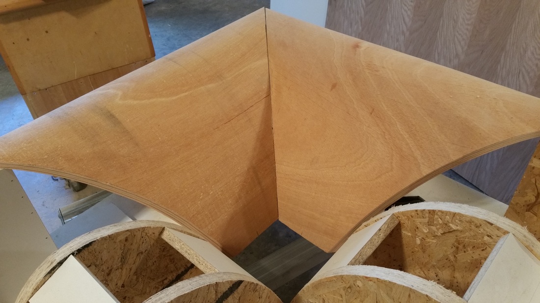 |
AuthorMark's Ramblings, show and tell. And other sundries. Archives
December 2019
Categories |
 RSS Feed